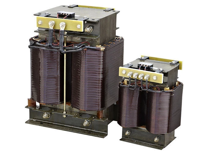
Ac Input Reactor
AC Reactors is used in variable frequency speed regulation to improve the input current waveform, increase the life of the rectifier and electrolytic filter capacitor, reduce the interference of bad input current waveform on the external power grid, and reduce the impact of power switching and three-phase imbalance. In situations with higher requirements, the reactor can be replaced by a more complex power quality filter unit. The use of voltage-type general-purpose inverter filter capacitors makes the input current spike pulse-shaped. When the grid impedance is small, this spike pulse current is extremely large, causing great harmonic interference and easily damaging the inverter rectifier bridge and capacitor. When the transformer capacity is more than 10 times greater than the inverter capacity, the internal resistance of the grid distribution transformer and transmission line cannot effectively suppress the spike pulse current, or when there is a thyristor device or a switch-controlled power factor compensation device on the same power supply, or when the three-phase power supply imbalance is greater than 3%, or when you want to improve the input side power factor and suppress odd harmonic interference, you should use an AC input reactor.
Generally speaking, the inductance of the AC input reactor of a voltage-type inverter can prevent the contactor from tripping due to sudden voltage by using a 3% voltage drop, and reduce the total current distortion to about 44% of the original value. In actual use, in order to reduce costs, an inductance of 2% voltage drop is usually used. Reactors with a voltage drop of 4% or more should be used in situations where harmonic suppression requirements are relatively high. Generally, 2%~4% voltage drop reactors are selected. This percentage is relative to the phase voltage, that is:
UK=△U/Up×100%
Where: △U—phase voltage drop
Up—phase voltage
When three phases, the inductance value of the AC reactor on the input side is:
L=(2~4)/[100(Up×10-3/2×3.14×f×I)] (Note 1)
Note 1: This is the original formula. The formula should be: L=(2~4)/[100(Up×10-3×2×3.14×f×I)] mH
The current value should be slightly larger than the rated current value to prevent overload operation; the inductance value is slightly larger, which is not a big problem. A larger value is beneficial to reduce harmonics. Customers also need to consider the internal impedance of the power supply. The power of the power transformer is greater than 10 times the power of the inverter, and the line is very short. The internal resistance of the power supply is small. Not only is it necessary to use an input AC reactor, but also to select a larger inductance value, such as an inductance of 4%~5% impedance.
It is better to use AC and DC reactors at the same time. Table 4 shows the harmonic suppression data of AC and DC reactors. Table 5 shows the harmonic suppression data of AC and DC reactors.
Note: AC reactor is 3%; the energy stored in the DC side reactor is equivalent to 0.08~0.15ms (100% load conversion); the energy stored in the main filter capacitor is equivalent to 15~30ms (100% load conversion); the load is 100%; according to the nth harmonic current = fundamental current × (nth higher harmonic current generation amount %)/100, calculate the harmonic current of each order.
Note: The test inverter is 45kW; the test current is 90~110A; the test instrument is FLUKE-43B power quality analyzer; the incoming AC reactor is 0.2mH (2% voltage drop reactor); the DC reactor inductance is 1.2mH; the load is a pure resistive load; according to the nth harmonic current = fundamental current × (nth higher harmonic current generation amount %)/100, calculate the harmonic current of each order.
 Русский
 Français
 Português
 Español
 اللغة العربية
