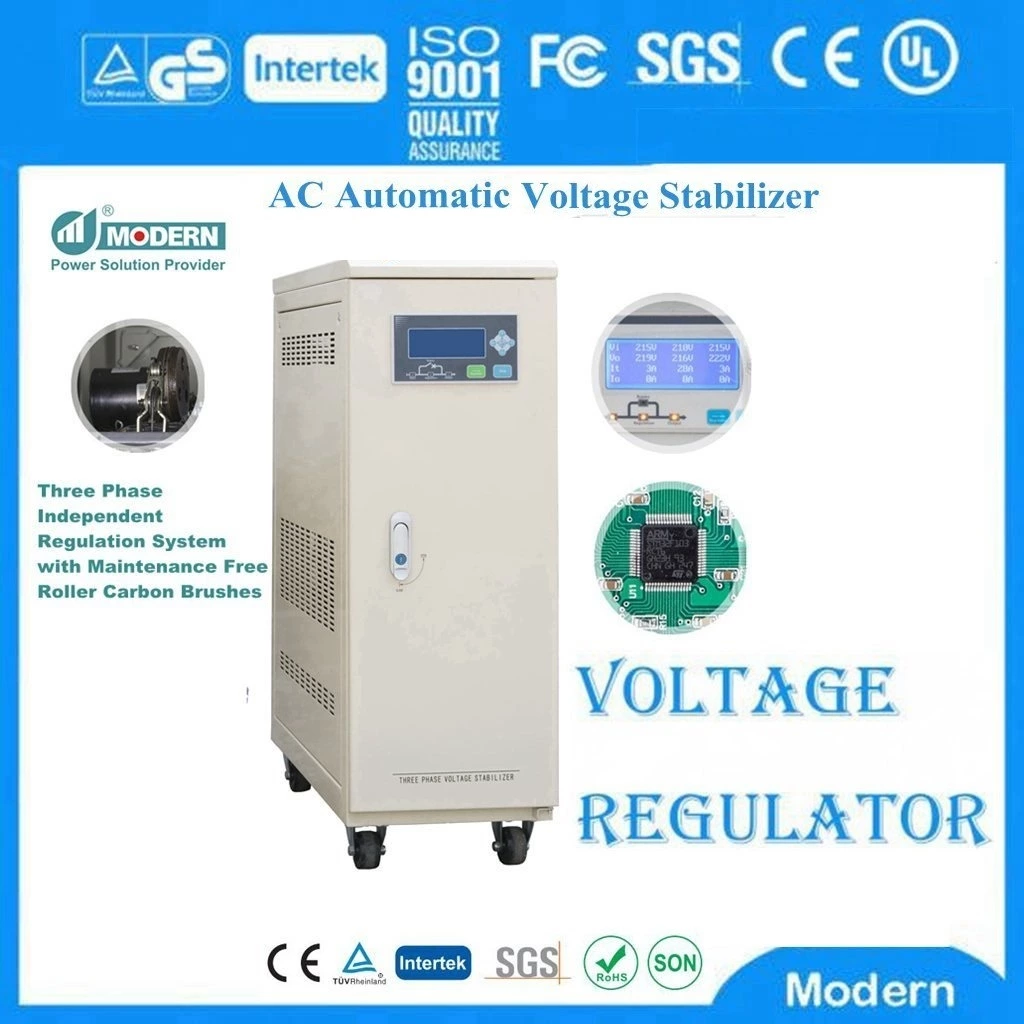
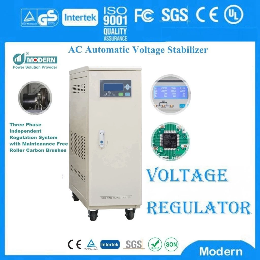
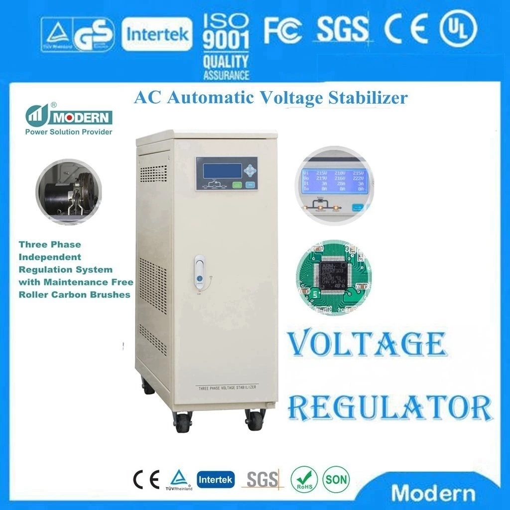
Dynamic Voltage Regulator, What Are The Error Marks Of The Voltage Regulator?
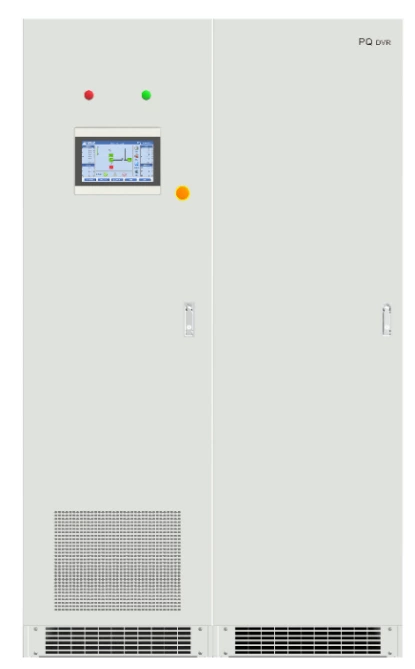
Dynamic Voltage Regulator (DVR)
The error flag is an open collector output that signals when the regulated output voltage drops below 5% (typical) of the rated output voltage. Initially, the error flag is low until the output voltage reaches 95% of the rated output voltage. In some cases, the error flag is delayed in the power conversion. This delay is set by an external capacitor and can be used as a power-on reset function to reset the microprocessor to power up. If the status "error" is indicated, the low condition of the output voltage causes the open collector output to be high (the flag transistor indicates OFF). This flag output is low when the output voltage is within 5% of the rated voltage.
Switching
The "on/off" or "shutdown" function allows the regulator to be turned on or off while powered. Although the regulator supply current is reduced to a lower level because the output is disabled in the "off" or "shutdown" mode, the internal bias circuits are still in operation. When re-enabled, the regulator will re-regulate the output voltage much faster than if the input voltage was turned off and on again. If the display is in the "on" state, the regulator will be enabled by a logic high level. Otherwise, it will be enabled by a logic low level.
Adjustment
In switching regulators and switched capacitor converters, an internal oscillator is used to set the switching frequency of the output transistors. The value of this switching frequency can determine some of the external components used in the converter, determine the frequency of the noise generated by the converter, and affect the performance of the converter. Some converters allow the switching frequency to be changed by adjusting the internal oscillator frequency ("frequency adjustment") or by synchronizing the oscillator with an external power supply ("synchronization"). Generally speaking, by increasing the switching frequency, smaller components (capacitors, inductors) can be used in the converter output stage. This can reduce the efficiency of the converter because of increased switching losses unless higher quality components are also used. A well-performing higher frequency converter will have a faster transient response than a lower frequency converter. If there are several converters on a board, it is usually best to synchronize them to a common source. This controls the noise generated by the entire batch and minimizes any "knock frequency" that may be generated. This issue is often important for high power converters (e.g. 5W or higher). In many cases, the switching frequency can only be increased from its preset value. The product data sheet will indicate the frequency range of this function.
 Русский
 Français
 Português
 Español
 اللغة العربية
