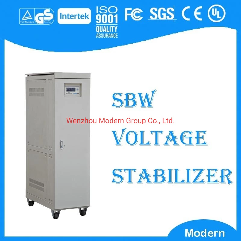
Stabilizer
A voltage stabilizer is a device that stabilizes the output voltage.
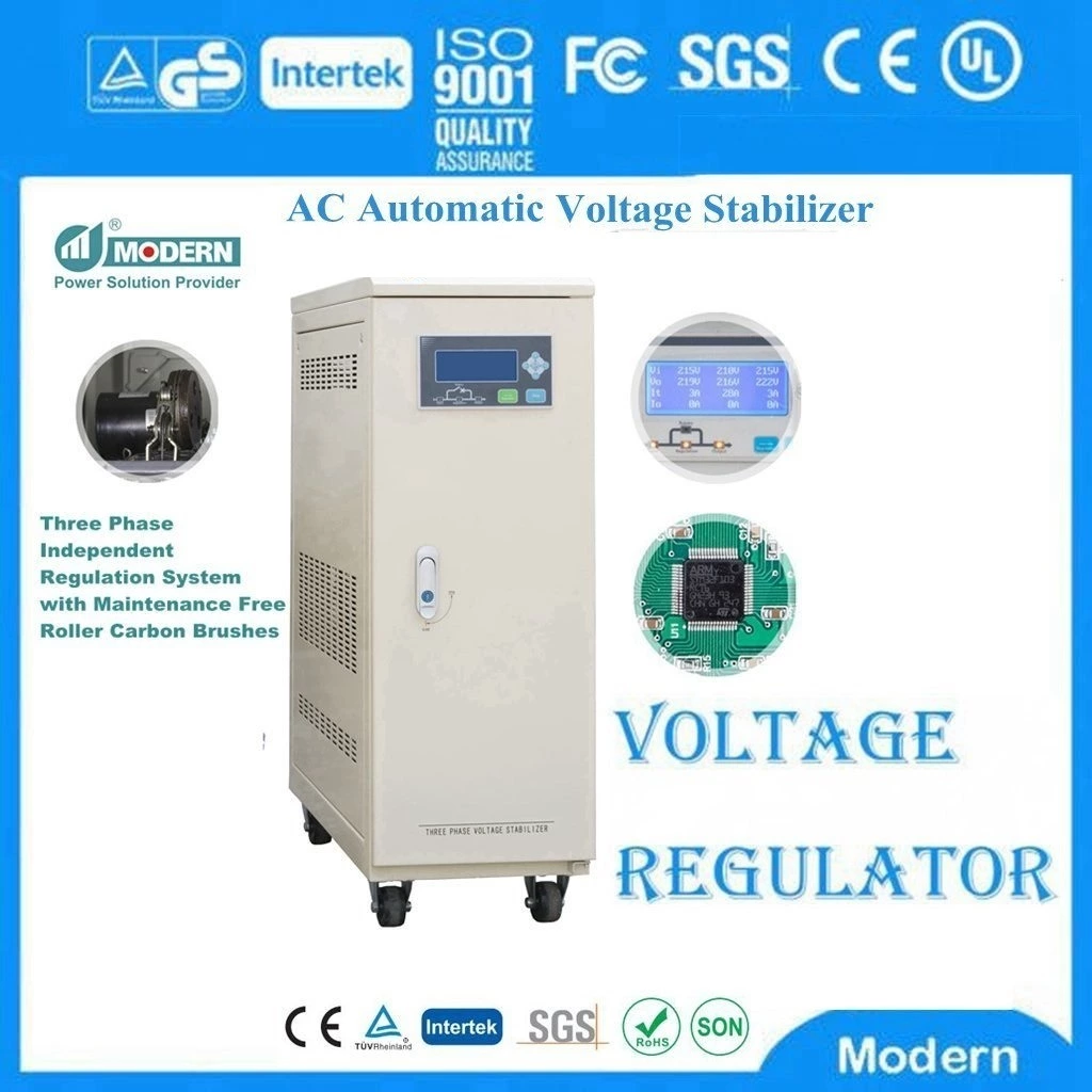
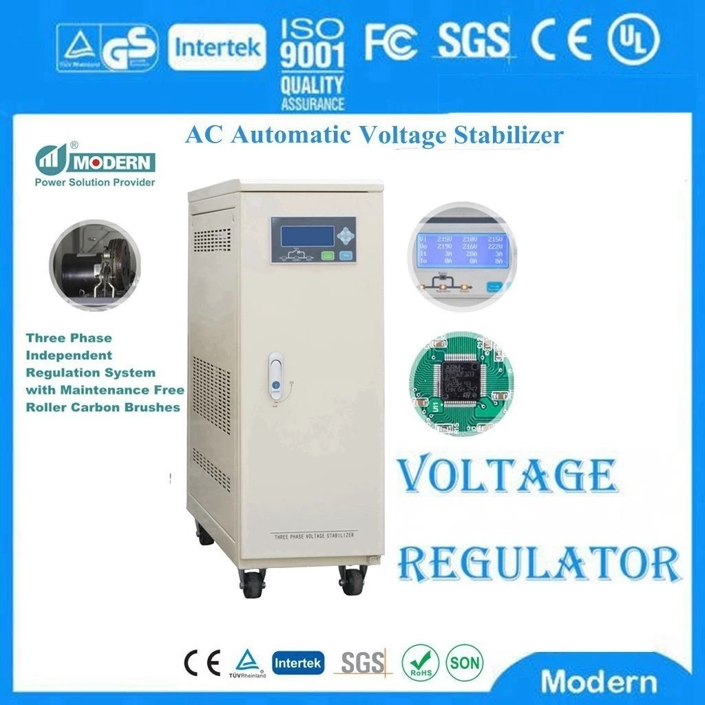
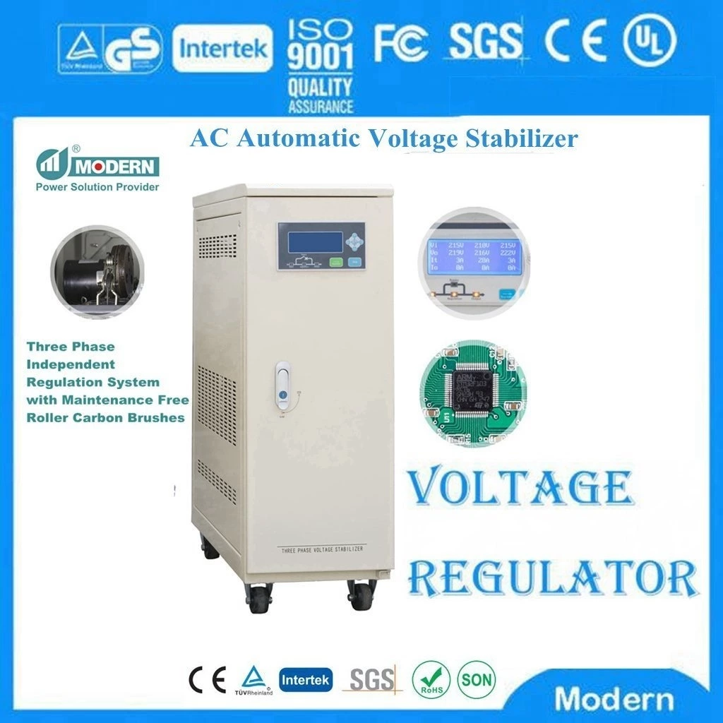
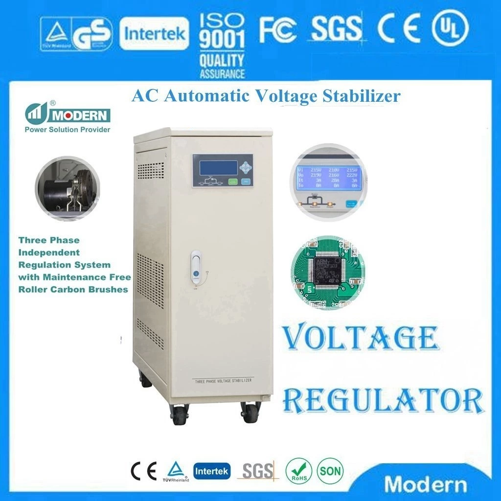
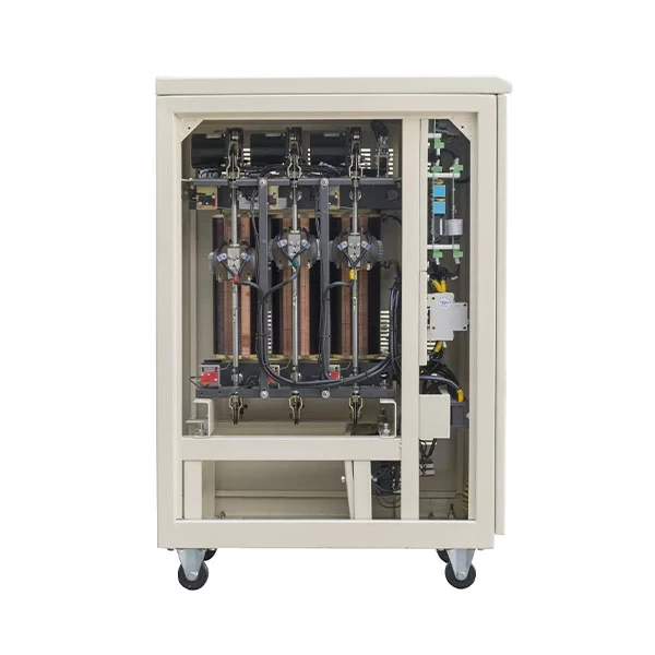
A mechanical voltage stabilizer consists of a voltage regulating circuit, a control circuit, and a servo motor. When the input voltage or load changes, the control circuit samples, compares, and amplifies, and then drives the servo motor to rotate, so that the position of the voltage regulator carbon brush changes, and the output voltage is kept stable by automatically adjusting the coil turns ratio.
The contactless voltage stabilizer uses a microcomputer (MCU+PLD+12-bit high-speed AD) for intelligent detection, and outputs instructions to control the rapid switching of the electronic module (IGBT or SCR), and maintains the stability of the output voltage through the principles of transformer frequency synchronization, phase locking, and sine wave superposition compensation.
Function introduction
A voltage stabilizer is a power supply circuit or power supply device that can automatically adjust the output voltage. Its function is to stabilize the power supply voltage that fluctuates greatly and does not meet the requirements of electrical equipment within its set value range, so that various circuits or electrical equipment can work normally under the rated working voltage. The original power voltage stabilizer relied on the beating of the relay to stabilize the voltage. When the grid voltage fluctuates, the automatic correction circuit of the power voltage stabilizer starts to activate the internal relay. Force the output voltage to remain near the set value. The advantage of this circuit is that the circuit is simple, but the disadvantage is that the voltage regulation accuracy is not high and each time the relay jumps and shifts gears, the power supply will be interrupted for a moment and spark interference will be generated. This has a great interference on the reading and writing work of the computer equipment, which can easily cause the computer to have an error signal, and in severe cases, it will also damage the hard disk. Most high-quality small voltage stabilizers use the method of motor dragging carbon brushes to stabilize the voltage. This type of voltage stabilizer has little interference to electrical equipment and relatively high voltage regulation accuracy.
Technical parameters
A. The voltage stabilizer has an input voltage adaptation range. The IEC standard is that the input voltage varies within the range of ±20 of the rated value. If it exceeds the range, an automatic sound and light alarm will be issued and the output voltage cannot be stabilized within the required range.
B. Output voltage regulation rate is the effect of the change in input voltage causing the change in output. When the load is the rated value, the input voltage is adjusted from the rated value to the upper limit and the lower limit according to the source voltage range, and the maximum change in output voltage (±) is measured. The smaller this value, the better, and it is an important indicator for measuring the performance of AC voltage stabilizers.
C. Load regulation rate: It is the effect of the change in load causing the change in output. Change the load current and measure the change in output voltage (±). The smaller this value is, the better. It is also an important indicator for measuring the performance of AC voltage stabilizers.
D. Output voltage relative harmonic content (also known as output voltage distortion), usually expressed as THD, is the ratio of the total effective value of harmonic content to the effective value of fundamental wave. When the load is rated and the input voltage distortion meets the reference conditions (generally less than 3), the output voltage distortion is measured when the input voltage is the lowest value, rated value and highest value, and the largest one is taken. The smaller this value is, the better.
E. Efficiency: It is the ratio (percentage) of the output active power P0 to the input active power Pi.
F. Load power factor
The capacity of the voltage stabilizer is expressed in volt-ampere (VA) or kilovolt-ampere (KVA). In addition to pure resistive loads, there are also inductive and capacitive loads in the load, that is, in addition to active power, there is also reactive power in the load. This pointer reflects the ability of the AC voltage stabilizer to carry inductive and capacitive loads.
For general AC stabilized power supply, the load power factor cosφ is 0.8. When the product is 1KW, the maximum output active power (i.e. the ability to carry resistive load) is 800W. If the product is expressed as 1KW (cosφ is still 0.8), the output active power is 1KW, and the output power S=1000/0.8=1250VA. When the load power factor value is small, it means that the power supply equipment has a strong ability to adapt to reactive loads.
G. The parameters of AC stabilizer include output power, input frequency, source frequency effect, random deviation (time drift), no-load input power, source power factor (this value is different from the load power factor, the larger the better, the maximum is 1), source current relative harmonic content, audio noise, etc., three-phase AC stabilized power supply, and three-phase output voltage imbalance, etc. The definition and test methods of these indicators can refer to relevant standards.
Scope of application
The voltage stabilizer can be widely used in: electronic computers, precision machine tools, computer tomography (CT), precision instruments, test equipment, elevator lighting, imported equipment and production lines in industrial and mining enterprises, oil fields, railways, construction sites, schools, hospitals, post and telecommunications, hotels, scientific research departments, etc., where stable power supply voltage is required. It is also suitable for users at the end of low-voltage distribution networks with low or high power supply voltage and large fluctuations, and for electrical equipment with large load changes. It is especially suitable for all places with high requirements for grid waveforms. High-power compensation power voltage stabilizers can be connected to thermal power, hydraulic power, and small generators.
Function introduction
Automatic Voltage Stabilizer is a power supply circuit or power supply equipment that can automatically adjust the output voltage. Its function is to stabilize the power supply voltage that fluctuates greatly and does not meet the requirements of electrical equipment within its set value range, so that various circuits or electrical equipment can work normally under the rated working voltage.
The original power voltage stabilizer relied on the jump of the relay to stabilize the voltage. When the grid voltage fluctuates, the automatic correction circuit of the power voltage stabilizer starts to activate the internal relay. The output voltage is forced to remain near the set value. The advantage of this circuit is that the circuit is simple, but the disadvantage is that the voltage stabilization accuracy is not high and every time the relay jumps and shifts, the power supply will be interrupted instantly and spark interference will be generated. This has a great interference on the reading and writing work of computer equipment, which can easily cause error signals in the computer and even damage the hard disk in severe cases. Most high-quality small voltage stabilizers use the method of motor dragging carbon brushes to stabilize the voltage. This type of voltage stabilizer has little interference on electrical equipment and relatively high voltage stabilization accuracy.
 Русский
 Français
 Português
 Español
 اللغة العربية
