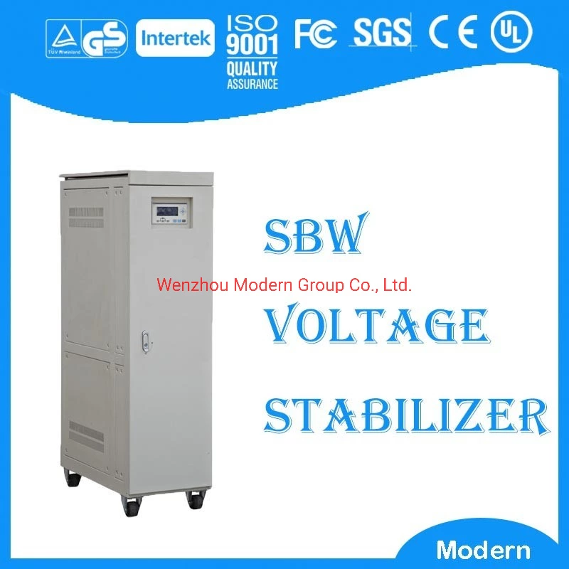
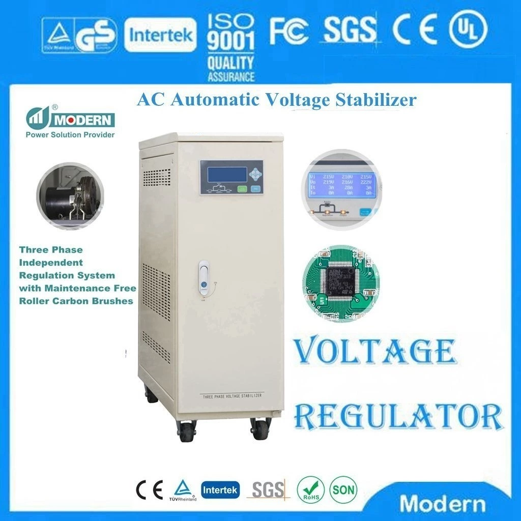
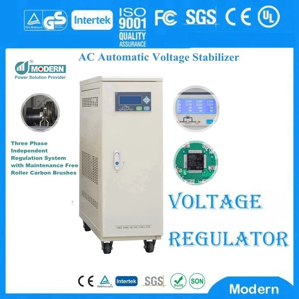
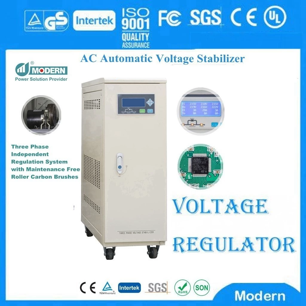
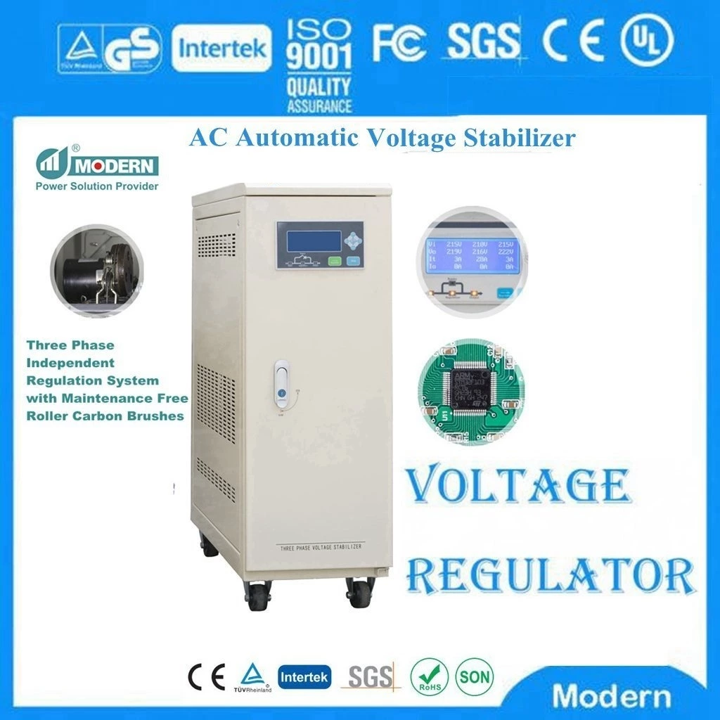
The Structure And Principle Of Automatic Voltage Stabilizer
The structure and principle are similar to those of a transformer. It uses a short-circuited moving coil on the same core to move up and down along the core column to change the impedance and voltage distribution of the other two coils with equal turns and anti-phase series connection to adjust the output voltage.
Schematic diagram of the wiring principle of Automatic Voltage Stabilizer. The core of the automatic voltage regulator is a single-phase single-column two-side yoke type, and sometimes a three-side yoke type. It has a main coil 1a and an auxiliary coil 1b, both of which have equal turns and are symmetrically sleeved on the upper and lower halves of the core column and connected in reverse series. The main coil 1a and coil 2 are autocoupled to each other to form an autotransformer. Coil 3 is a short-circuited moving coil, which is sleeved outside coils 1a, 1b and 2. The moving coil can change its position by means of a transmission mechanism, so that the output voltage U2 can be adjusted.
Changing the relative position between the moving coil of the automatic voltage regulator and the main coil and the auxiliary coil will change the impedance of the latter two coils, and the power supply voltage U1 will be distributed to the main and auxiliary coils according to the impedance. When the moving coil completely overlaps with the main coil, the impedance of the main coil is small, and the impedance of the auxiliary coil is, so U2 is small; conversely, when the moving coil completely overlaps with the auxiliary coil, U2 is. When the moving coil gradually moves from top to bottom, U2 can gradually increase from 0 to the value.
If three automatic voltage stabilizer units are installed on the same base and share a transmission mechanism, they can be connected into an automatic voltage stabilizer according to the three-phase connection method (generally Y connection method).
 Русский
 Français
 Português
 Español
 اللغة العربية
