What Is The Construction Principle Of A Voltage Stabilizer?
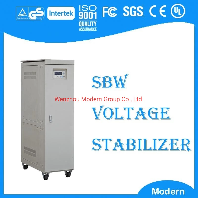
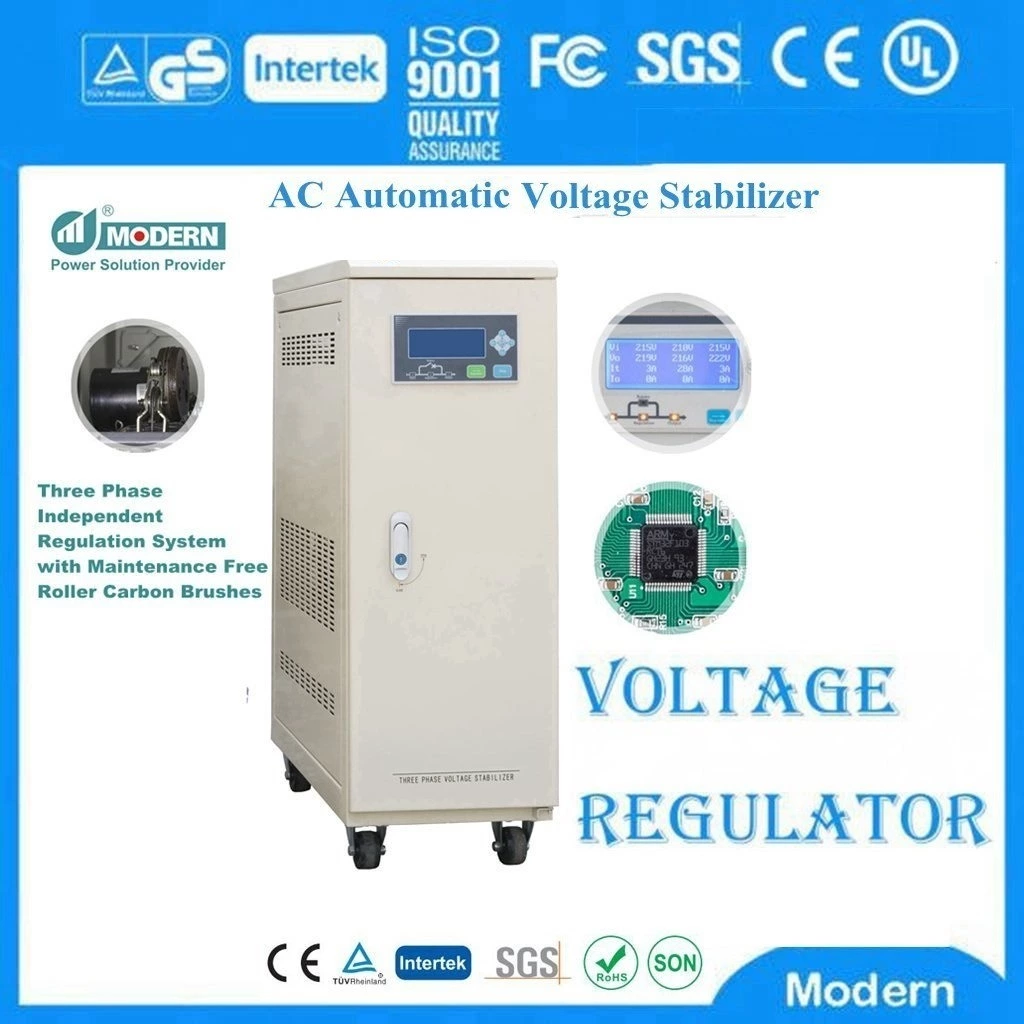
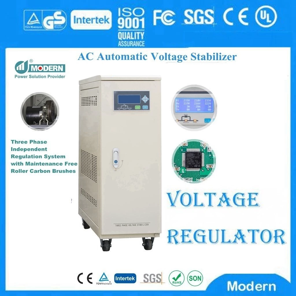
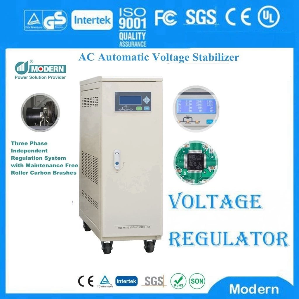
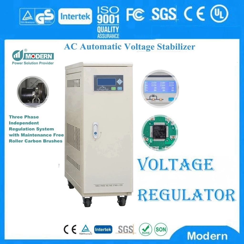
Wide Range Voltage Stabilizer is a device that stabilizes the output voltage. The wide range voltage regulator consists of a voltage regulating circuit, a control circuit, and a servo motor. When the input voltage or load changes, the control circuit samples, compares, and amplifies, and then drives the servo motor to rotate, so that the position of the voltage regulator carbon brush changes, and the output voltage is kept stable by automatically adjusting the coil turns ratio.
A typical switched capacitor converter includes four large MOS switches, and its switching sequence is a typical switch, doubling or halving the input power supply voltage. The transfer and storage of energy is provided by external capacitors. The company gives an example. With the problems of my country's isolation transformer products in the market environment, operation, product import and export, industry investment environment and sustainable development, my country has made a qualitative and quantitative analysis and forecast of the industry development trend on this basis. Engaged in transformers, wide range voltage stabilizers, voltage regulators and other low voltage supporting products, research and development, sales, "adhering to corporate innovation, the main products are: wide range voltage stabilizers, SBW-F sub-modulation power voltage stabilizers, SVC high-precision fully automatic AC voltage stabilizers, precision purification voltage stabilizers, microcomputer contactless voltage stabilizers, SGSBK isolation transformers, OSGQZB autotransformers, ZSGZDG rectifier transformers, SSG servo transformers, DN resistance welding water-cooled transformers, reactors, contact autovoltage regulators, column high-power electric voltage regulators and other complete sets of electrical equipment. The product design is novel, small in size, beautiful in appearance, with the advantages of low loss, low noise, and impact resistance. It is widely used in industrial and mining enterprises, textile machinery, printing and packaging, petrochemicals, schools, shopping malls, elevators, post and telecommunications, medical machinery and other occasions that require normal voltage guarantee.
In the first part of the switching cycle, the input voltage acts on a capacitor (C1). In the first part of the switching cycle, the charge is transferred from C1 to the first capacitor C2 The traditional switched capacitor converter is constructed as an inverter, where C2 has a grounded positive terminal and its negative terminal delivers a negative output voltage. After a few cycles, the voltage across C2 will be applied to the input voltage. Assuming there is no load on C2, no losses in the switch, and no continuous resistance in the capacitor, the output voltage will be exactly the negative of the input voltage. In reality, the efficiency of the charge transfer (and therefore the stability of the output voltage) depends on the switching frequency, the resistance of the switch, the value of the capacitor, and the continuous resistance. A similar topology, the voltage doubler, uses the same switches and capacitor bank, but changes the ground connection and input voltage. Other more complex variants use additional switches and capacitors to achieve other ratios of input voltage to output voltage, and in some cases, use specialized switching sequences to produce fractional relationships (such as 3/2). In their simplest forms, switched capacitor converters are unregulated. Some new National Semiconductor switched capacitor converters have automatically adjusted gain levels to produce a regulated output; others use a built-in low-dropout linear regulator to produce an unregulated output.
 Русский
 Français
 Português
 Español
 اللغة العربية
