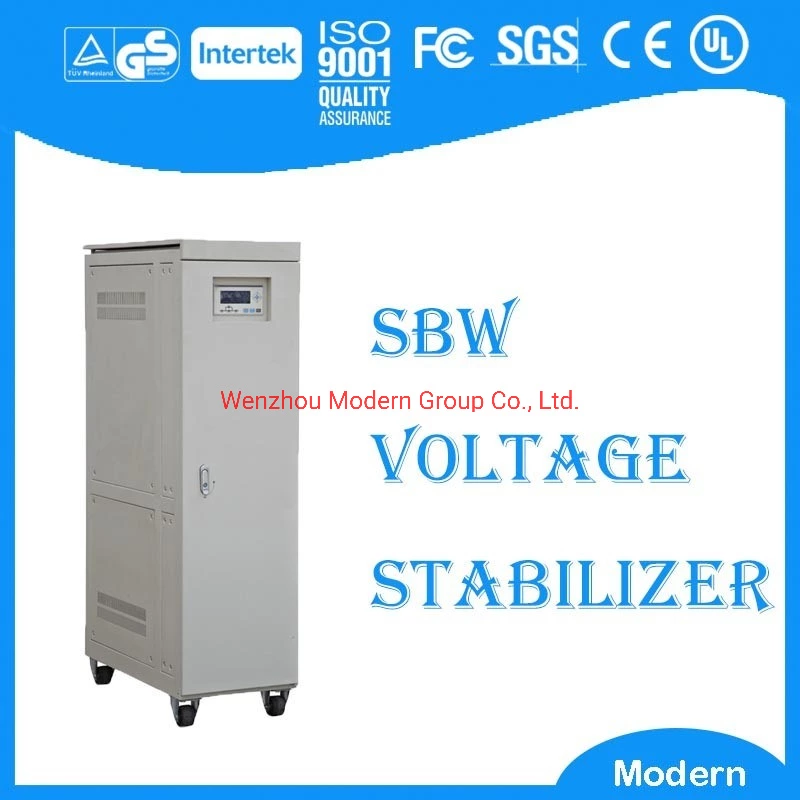
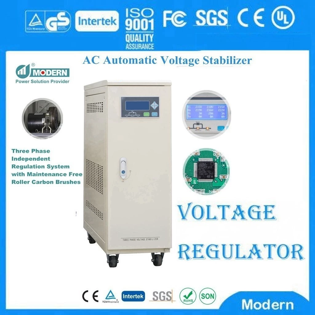
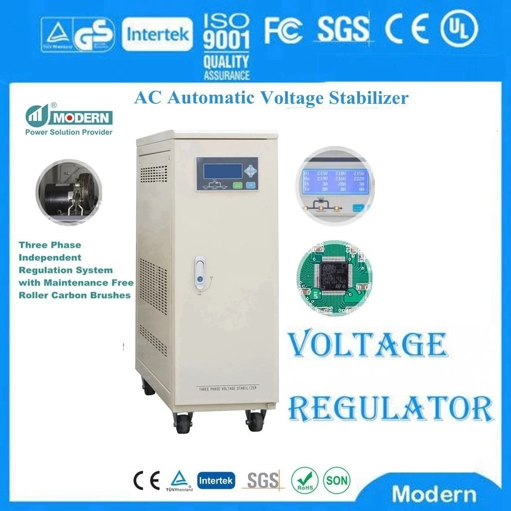
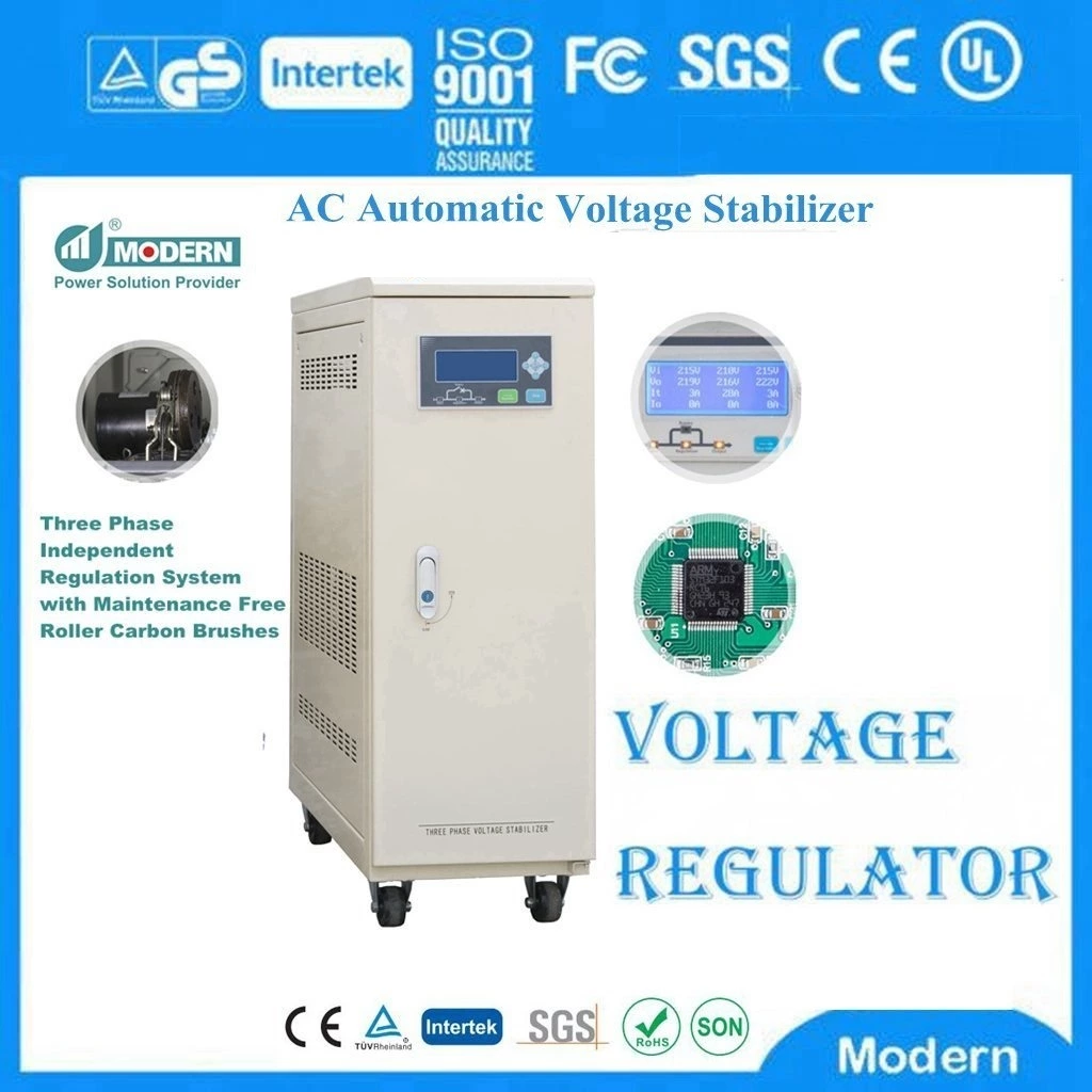
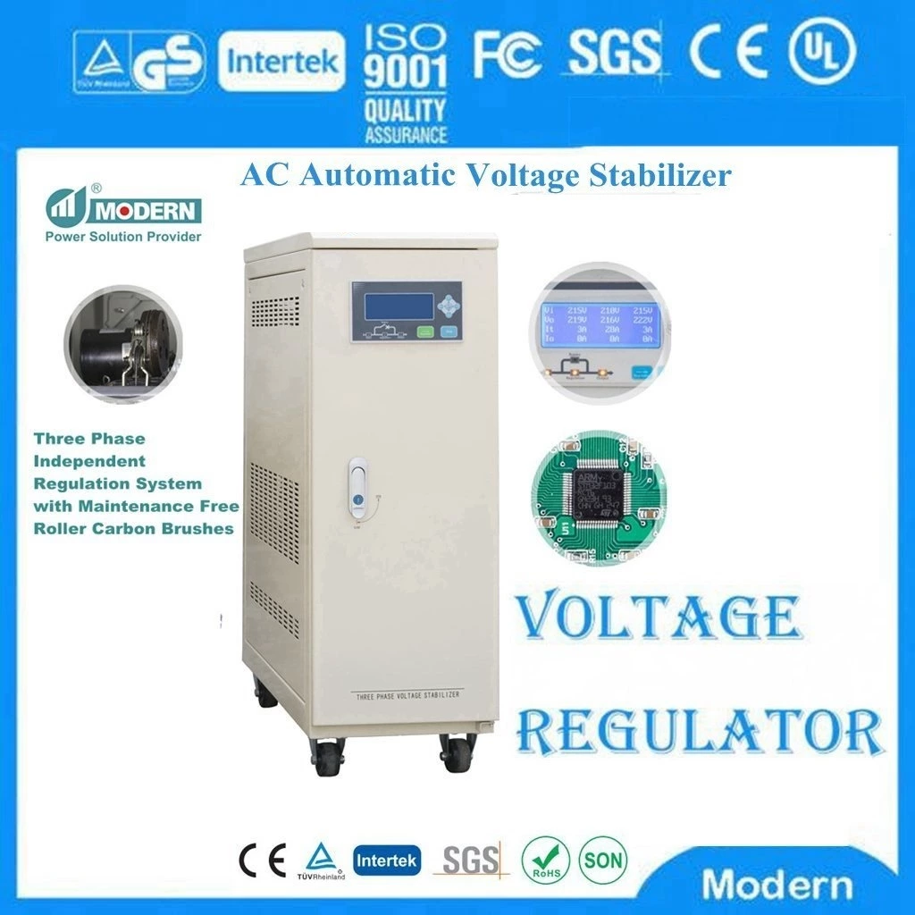
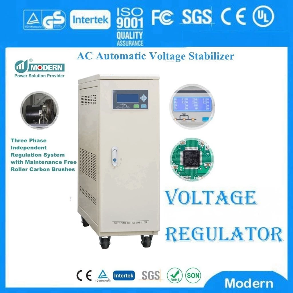
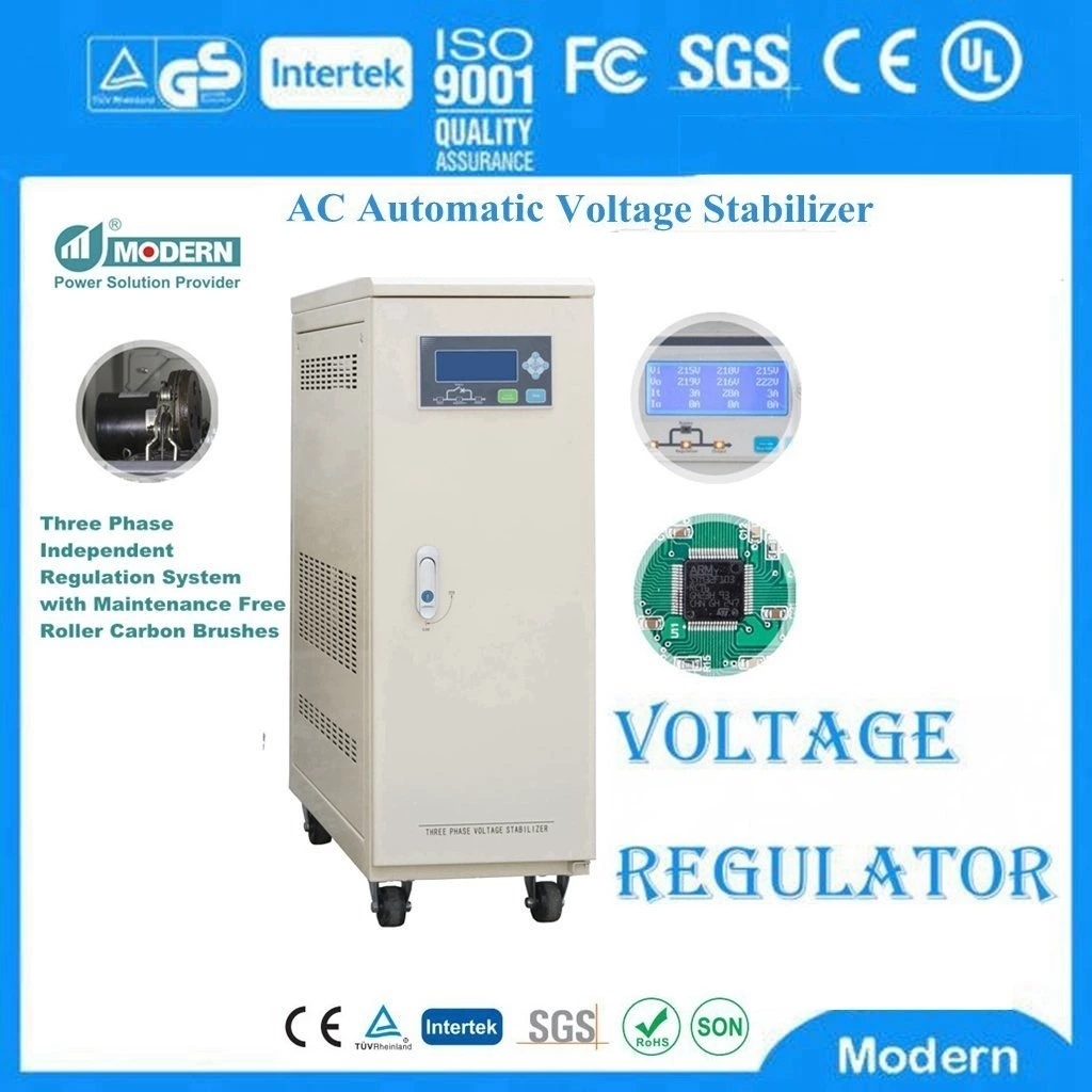
Working Principle Of Ac Voltage Stabilizer
Automatic Voltage Stabilizer Working principle
I. Classification of voltage stabilizers 1
According to different voltage regulation methods, it can be divided into:
1 Oil-immersed voltage stabilizer, i.e. electronic induction oil-type voltage stabilizer
2 Dry voltage stabilizer: contact voltage regulator and contactless voltage stabilizer
II. Classification of voltage stabilizers 2
According to different power supply use environments, it can be divided into two categories:
1 Single-phase AC voltage stabilizer
2 Three-phase AC voltage stabilizer
III. Analyze the working principle of voltage stabilizer by taking dry contact voltage regulator as an example:
Analysis of the principle of single-phase AC voltage stabilizer
1. Analysis of the principle of single-phase direct voltage regulator
Point A is the input side of the single-phase voltage regulator, and point B is the output side of the single-phase voltage regulator.
In fact, this type of voltage regulator that uses a voltage regulator to directly adjust the voltage is made using the principle of an autotransformer. The AN side in the figure is the input side of the autotransformer, and the BN side is the output side of the autotransformer. If the input voltage is higher than the output setting point 220V, the autotransformer works in a step-down state. If the input voltage is lower than 220V, the autotransformer works in a step-up state.
The main difference between this type of voltage regulator and the autotransformer is that the input point A can be adjusted from 0V to 250V. V. In this way, the input point of the input voltage can be adjusted at any time to meet the constant output voltage. Generally, we call point A on the input side the sliding arm, which is driven by the motor through the reduction device, and the direction of the motor is controlled by the voltage stabilization control circuit. The sampling circuit of the voltage regulator always monitors the voltage between the two output points of the voltage regulator. When the output voltage increases, the motor is controlled to move in the direction of the autotransformer step-down. When the output voltage reaches the desired voltage, the motor control movement is stopped. On the contrary, the control circuit controls the motor to rotate in the direction of the autotransformer step-up. Stop when the desired voltage is reached.
The capacity of this type of voltage stabilizer is entirely borne by the autotransformer of the output voltage transformer, but due to the influence of its manufacturing process, it cannot be made very large and can only be adapted to low-power occasions. To increase the power of the voltage stabilizer, a compensation transformer must be added to achieve power expansion of the voltage stabilizer
2. Analysis of the principle of single-phase compensation voltage stabilizer
In the main circuit, then, the main energy output by this voltage stabilizer is directly added to the output load through the low-voltage side coil of the compensation transformer. As long as the wire diameter of the secondary coil of the compensation transformer is large enough,
the power of the voltage stabilizer can be made very large. The voltage regulating transformer T1 only needs The difference between the input voltage and the output voltage is borne according to the allowable input variation range of the voltage regulator. The power of the voltage regulator transformer T1 is often a fraction of the actual capacity of the voltage regulator. The size of the voltage regulator transformer is determined by the parameter of the voltage regulator ratio.
Let's analyze its working principle below:
The voltage regulator transformer is mainly responsible for providing compensation voltage. The size and direction of this compensation voltage can be changed according to the movement of the sliding arm of the voltage regulator transformer. This can obtain a compensation voltage with a changeable size and direction on the low-voltage side of the compensation transformer. This voltage will be vector-superimposed with the voltage provided by the input end. The output voltage is stable at the required setting point.
Let's take an example:
The input voltage is U1=240V, and the output voltage is required to be stable at UO=220V. Then there is the following equation:
UO=U1-△U
That is, the direction of △U should be opposite to the direction of U1, and the magnitude is exactly 20V. The input voltage is U1=200V, and the output voltage is required to be stable at UO=220V. Then there is the following equation:
UO=U1+△U
That is, the direction of △U should be the same as the direction of U1, and the magnitude is exactly 20V. From the above formula, it can be seen that the compensation voltage △U is generated by the voltage regulating transformer. The voltage is transmitted to the high-voltage side of the compensating transformer and then induced to the low-voltage side of the compensating transformer through the iron core, and then vector-superimposed with the input voltage. The compensating transformer is mainly responsible for the transmission of the compensating voltage, while the voltage-regulating transformer is responsible for providing the compensating voltage whose direction and magnitude can be changed. Let's analyze how the voltage-regulating transformer changes the direction and magnitude of the compensating voltage: As can be seen from Figure 5, the C.D points of the voltage-regulating transformer are connected across the 220V voltage. And point E happens to be the center point of the voltage-regulating transformer. We assume that the sliding arm stops at point C. Then the voltage applied to the high-voltage side of the compensating transformer is higher than point G at point F, and the current flows from point F to point G.
When the sliding arm stops at point D, the voltage applied to the high-voltage side of the compensating transformer is higher than point F at point G, and the current flows from point G to point F. In this way, the compensating voltage applied to the compensating transformer changes direction.
So how does the voltage regulator change the size of the compensation voltage? Of course, it is also achieved by moving the sliding arm. When the sliding arm is away from the center point E of the voltage regulator, the voltage obtained at the high-voltage side of the compensation transformer, F and G, is higher, and vice versa. When the input voltage of the voltage regulator is exactly 220V, when the sliding arm moves to point E, the compensation voltage between points F and G is 0. The low side of the compensation transformer is neither added nor subtracted. The output voltage is the input voltage.
IV. Working principle of three-phase voltage regulator:
The three-phase voltage regulator actually connects three voltage regulator units together in a "Y" connection. Then use the control circuit board and motor drive system The voltage regulator is controlled by the system to achieve the function of stabilizing the output voltage. If the sliding arms of the three voltage regulators are driven by one motor, the voltage regulation method is a unified voltage regulator. If the sliding arms of the three voltage regulators are independently adjusted by three motors, the voltage regulator is a three-phase separate voltage regulator. Their working principles are exactly the same as those of single-phase voltage regulators.
V. How does the voltage regulator ensure continuous output
During the voltage regulation process, the voltage regulator changes the number of coil turns in contact by moving the carbon brush. Therefore, it is required to keep in contact with the coil at all times during the adjustment. Otherwise, there will be a power outage.
How does the voltage regulator maintain continuous output?
1. The carbon brush must have a certain thickness.
2. Before the carbon brush has completely moved away from the coil that it has already touched, the carbon brush has already touched another turn of the coil.
3. Two turns must be bridged during movement (at least two turns)
4. There is always a short circuit between turns during the operation of the voltage regulator. The thicker the carbon brush, the more turns will be short-circuited. Therefore, the thickness of the voltage regulator carbon brush varies according to the wire diameter of the voltage regulator.
5. Because the short circuit between turns is harmful and useless, it will cause short-circuit circulation, so its size must be controlled. Therefore, the turn voltage of the voltage regulator is generally below 1V. The turn voltage of the common high-power voltage regulator is 0.8-0.9V, and the low-power is even smaller, generally ranging from 0.4-0.7V. If the turn voltage is too high, the stability of the voltage regulator will be worse and it will be easily burned.
 Русский
 Français
 Português
 Español
 اللغة العربية
