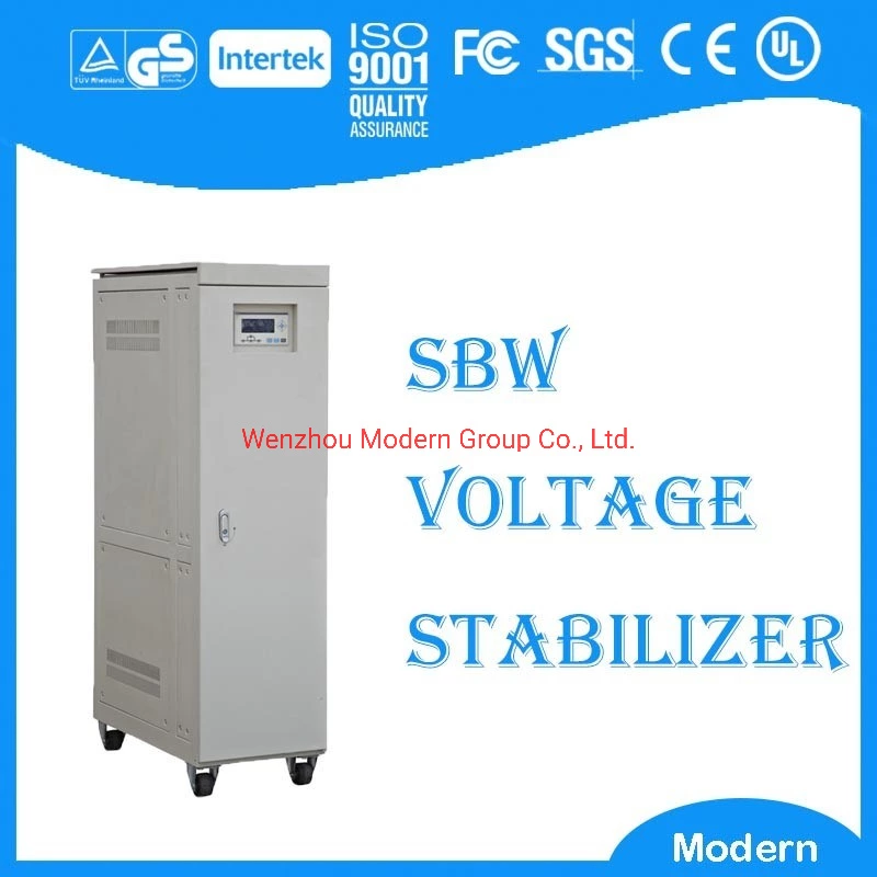
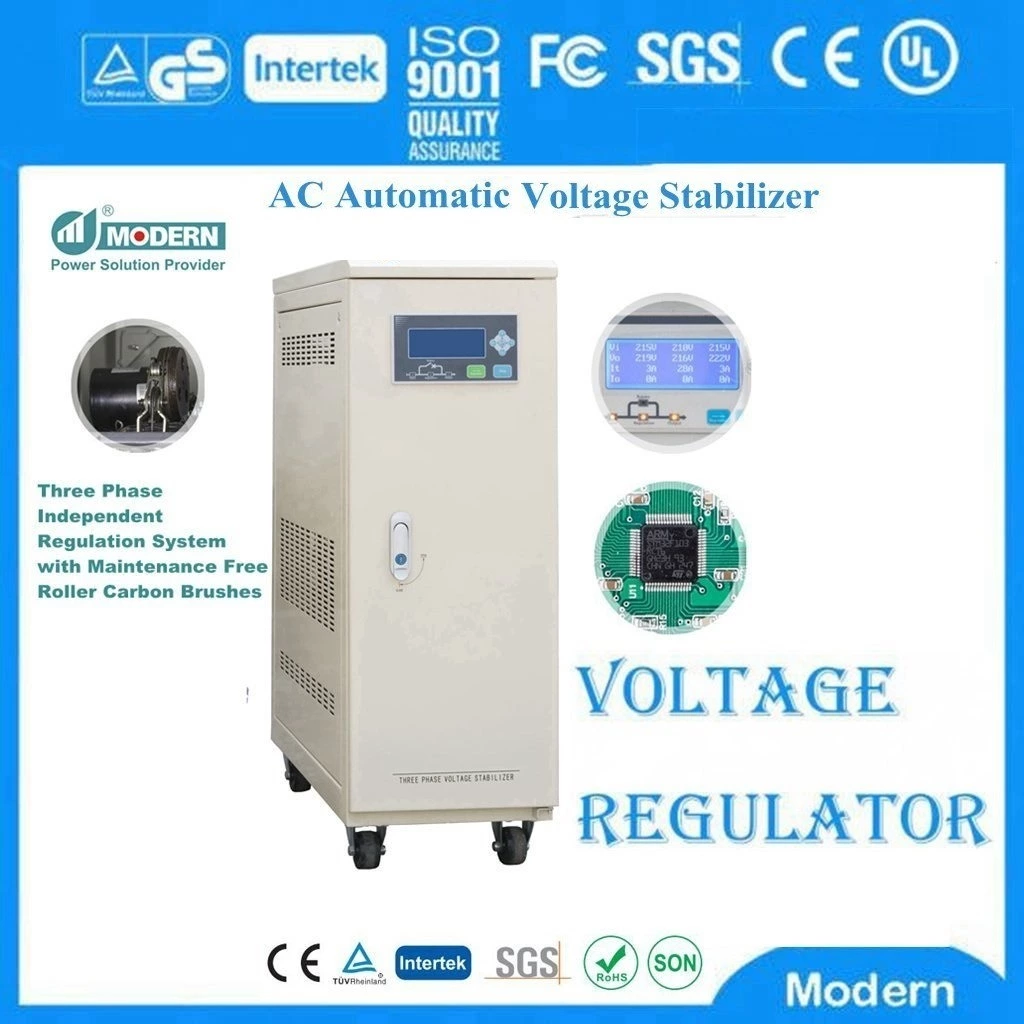
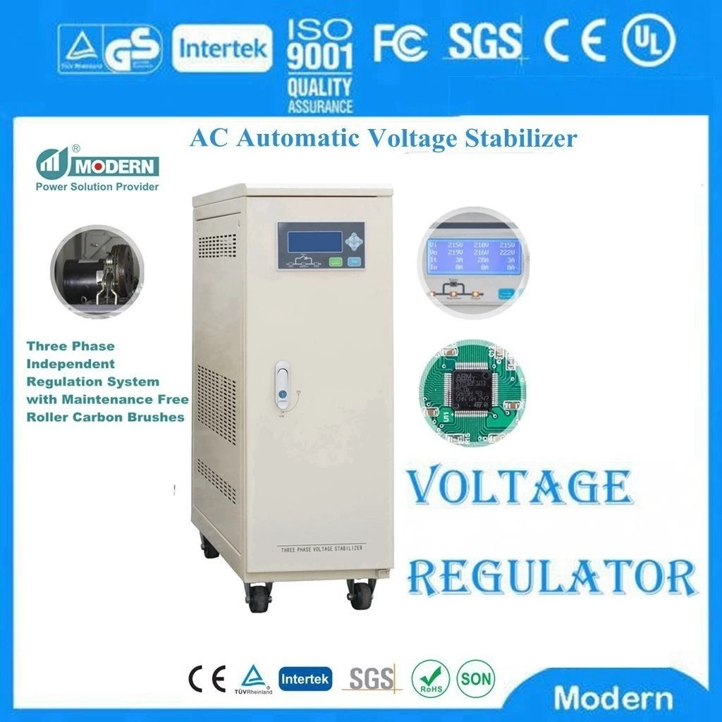
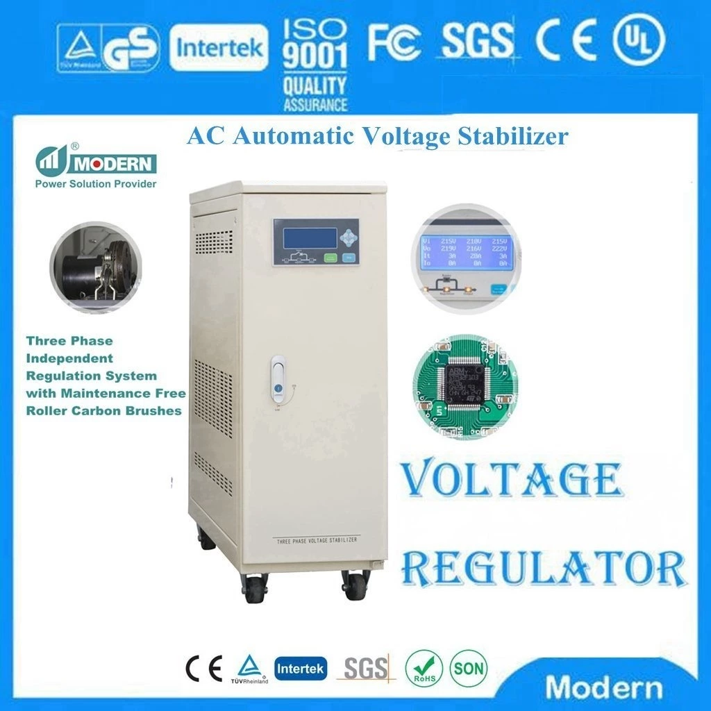
You Must Learn How To Operate The Voltage Stabilizer
FAULT FLAGS
The FAULT FLAGS are open collector outputs that signal when the regulated output voltage drops below 5% (typical) of the rated output voltage. Initially, the FAULT FLAGS are low until the output voltage reaches 95% of the rated output voltage. In some cases, the FAULT FLAGS are delayed in the power conversion. This delay is set by an external capacitor and can be used as a power-on reset function to reset the microprocessor to power up. If the status "FAULT" is indicated, the output voltage low condition causes the open collector output to be high (flag transistor indicates OFF). The flag output is low when the output voltage is within 5% of the rated voltage.
SWITCH
The "ON/OFF" or "SHUTDOWN" function allows the Static Voltage Stabilizer to be turned on or off while powered on. Although the regulator supply current is reduced to a lower level in the "OFF" or "SHUTDOWN" mode because the output is disabled, the internal bias circuits are still operational. When re-enabled, the regulator will re-regulate the output voltage much faster than if the input voltage was turned off and on again. If the display is in the "on" state, the regulator will be enabled by a logic high level. Otherwise, it will be enabled by a logic low level.
Adjustment
In switching regulators and switched capacitor converters, an internal oscillator is used to set the switching frequency of the output transistors. The value of this switching frequency can determine some of the external components used in the converter, determine the frequency of the noise generated by the converter, and affect the performance of the converter. Some converters allow the switching frequency to be changed by adjusting the internal oscillator frequency ("frequency adjustment") or by synchronizing the oscillator with an external power supply ("synchronization"). In general, by increasing the switching frequency, smaller components (capacitors, inductors) can be used in the converter output stage. This can reduce the efficiency of the converter because of increased switching losses unless higher quality components are also used. A well-performing higher frequency converter will have a faster transient response than a lower frequency converter. If there are several converters on a board, they are usually synchronized to a common source. This controls the noise generated by the entire batch and minimizes any "knock frequency" that may be generated. This issue is often important for high power converters (e.g. 5W or higher). In many cases, the switching frequency can only be increased from its preset value. The product data sheet will indicate the frequency range of this function. [1]
Capacity curve
When the input phase voltage of the auto-coupling voltage regulator (single-phase 0.5kVA~3kVA, 10k horizontal and below, three-phase 9kVA and below) is lower than 198V, the output capacity begins to decrease; when the input phase voltage is equal to 160V, it drops to 50% of the rated capacity of the voltage regulator. Therefore, at the low end of the power supply voltage, special attention should be paid to reducing the load and derating to avoid overloading and burning the voltage regulator;
The auto-coupling voltage regulator can output both 220V and 110V voltages at the same time. However, even when all outputs are 110V, the load carried by the voltage regulator cannot exceed 50% of the rated capacity, otherwise it will be overloaded.
⒈ Connect the voltage regulator input to the distribution board, and install a fuse that meets the power protection rate of this instrument on the user's distribution board to ensure power safety.
⒉ Connect the power supply of the electrical equipment to the output terminal of this instrument. Note that the rated input voltage value of the electrical equipment should be consistent with the output of the voltage stabilizer. Do not connect it wrongly.
⒊ Turn on the power switch of the voltage stabilizer first, and the working indicator light will light up. Observe whether the voltage meter indication value is normal. When the output voltage is normal, turn on the power switch of the electrical equipment again, and this voltage stabilizer can automatically adjust the voltage and supply power normally.
⒋ When the electrical equipment is not used for a long time, please turn off the power switch of the electrical equipment to reduce power consumption and extend the service life of the voltage stabilizer.
⒌ The voltage stabilizer must not be overloaded. When the mains voltage is low, the output capacity is reduced, and the voltage stabilizer load should be reduced accordingly.
⒍ When the electrical appliances such as refrigerators, air conditioners, water pumps, etc. are selected, a voltage stabilizer with a capacity of more than 3 times should be selected to prevent the equipment startup current from exceeding the voltage stabilizer fuse current or the overcurrent protection circuit breaker current, causing the voltage stabilizer fuse to melt or the circuit breaker to trip or the voltage drop to be too large to work.
⒎ The wire connected to the voltage stabilizer should have enough load surface to prevent heating and reduce voltage drop. Voltage stabilizers with a capacity of more than 2KVA use terminal connection. A single copper wire should be selected and the terminal screws should be tightened as much as possible to prevent heating at the connection.
⒏ Whether it is a single-phase or three-phase voltage stabilizer, after connecting all input and output lines, the power switch of the load should be turned off first, then the voltage stabilizer should be turned on. After checking that the output voltage is normal, the power switch of the load should be turned on.
The saturation characteristics of the core material are used to highlight the basic stability of the output voltage.
Advantages: reliable operation, strong overload capacity, automatic protection when the output is short-circuited, simple structure, large voltage stabilization range, and strong anti-interference ability.
Disadvantages: heavy weight, large volume, high price, high noise, high core temperature rise, and high requirements for the input power supply working frequency.
Applications: computer-related products, medical monitoring systems, program control systems, automatic testing equipment, radio and television equipment, postal and telecommunications equipment, automatic plug-in machines, wires, printing equipment, plastic injection equipment, ATMs, SMT equipment, scientific research experiments, etc.
Basic structure of magnetic amplification AC voltage stabilizer
The output voltage is stabilized by changing the magnetic resistance of the magnetic amplification transformer connected in series with the primary circuit of the autotransformer.
Advantages: high voltage regulation accuracy and fast response time
Disadvantages: heavy weight, large volume and high price.
Applications: precision electronic equipment, medical equipment, computer rooms, laboratories, product aging and testing.
 Русский
 Français
 Português
 Español
 اللغة العربية
